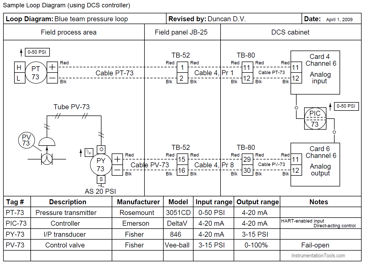
Loop Wiring Diagram Instrumentation
Honda Xr200 Wiring Diagram, Skygo150 Voltage Regulator for XR200/Actual Wiring/Honda XR200 Modified/Supermoto/DIY Garage PH, 10.03 MB, 07:18, 10,383, D I Y Garage PH, 2021-01-23T08:48:03.000000Z, 19, Iam looking for a 1982 honda xr200 wiring diagram, www.justanswer.com, 904 x 703, jpeg, wiring diagram 1982 honda xr200 xt200 yamaha manual iam motorcycle looking 1981 mechanic bikee wire, 20, honda-xr200-wiring-diagram, Anime Arts
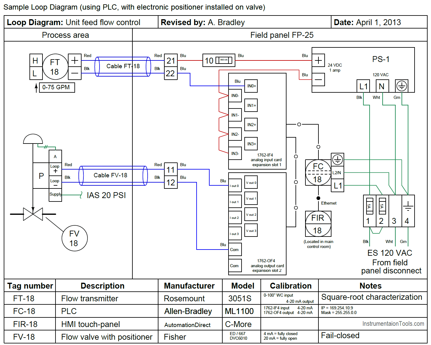
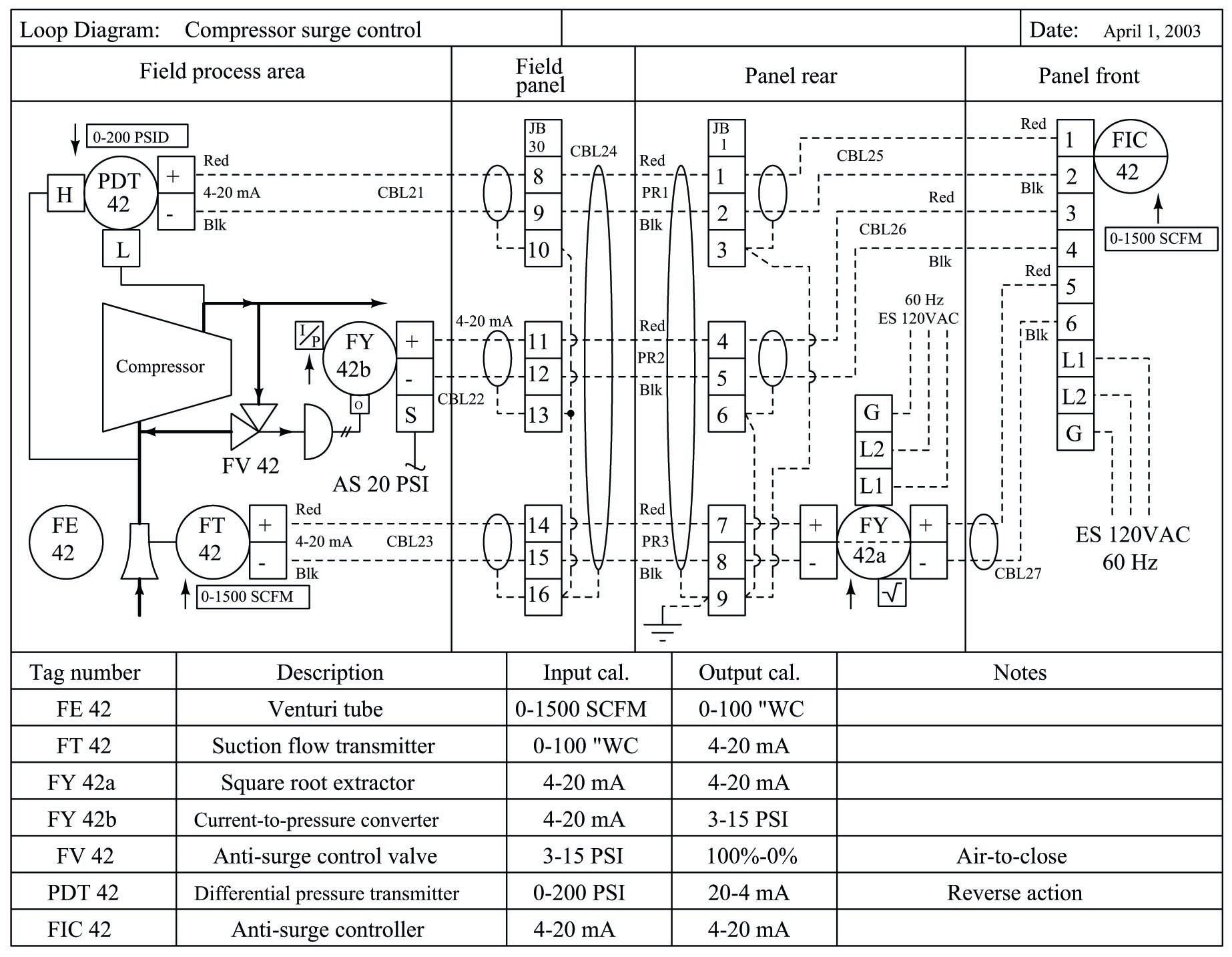
P&ids and loop diagrams are construction and documentation drawings that depict the flow of the process and illustrate the instrumentation control and measurement interactions, wiring and connections to the process. The process is illustrated in. In this lesson we go over the ever important and go to document as an instrument technician and that is the loop diagram. We talk about what they are, how th.
Mainly for construction contractor who will install and wire all the loops. It helps them to track each and every tag correctly and easily while keeping log of the activities. Although wiring data can be imported, the intricate nature of instrumentation usually prevents a fully automated approach, and so wiring is still performed manually to make sure it matches the intended design. There are two types of loops are in the field of instrumentation. It has no feed back. 2. close loop :it has feed back. In instrumentation a close loop is consist of 3 basic parts. 1. input device (pressure ,level ,flow ,temperature transmitters) 2. output device (control valve) 3. controller (dcs, plc , etc. ) Instrumentation loop test loop checking | paktechpoint.
Instrumentation Loop Diagrams - InstrumentationTools

Basics of Instrument Loop Diagrams ~ Learning Instrumentation And Control Engineering

Instrumentation Loop Diagrams - InstrumentationTools
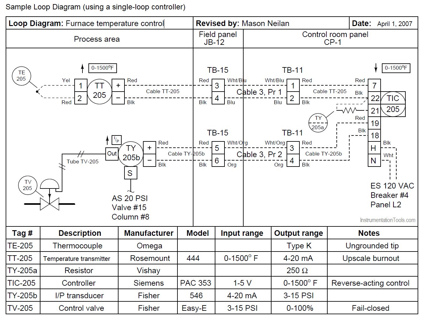
15 Loop Diagram Questions - Instrumentation Tools
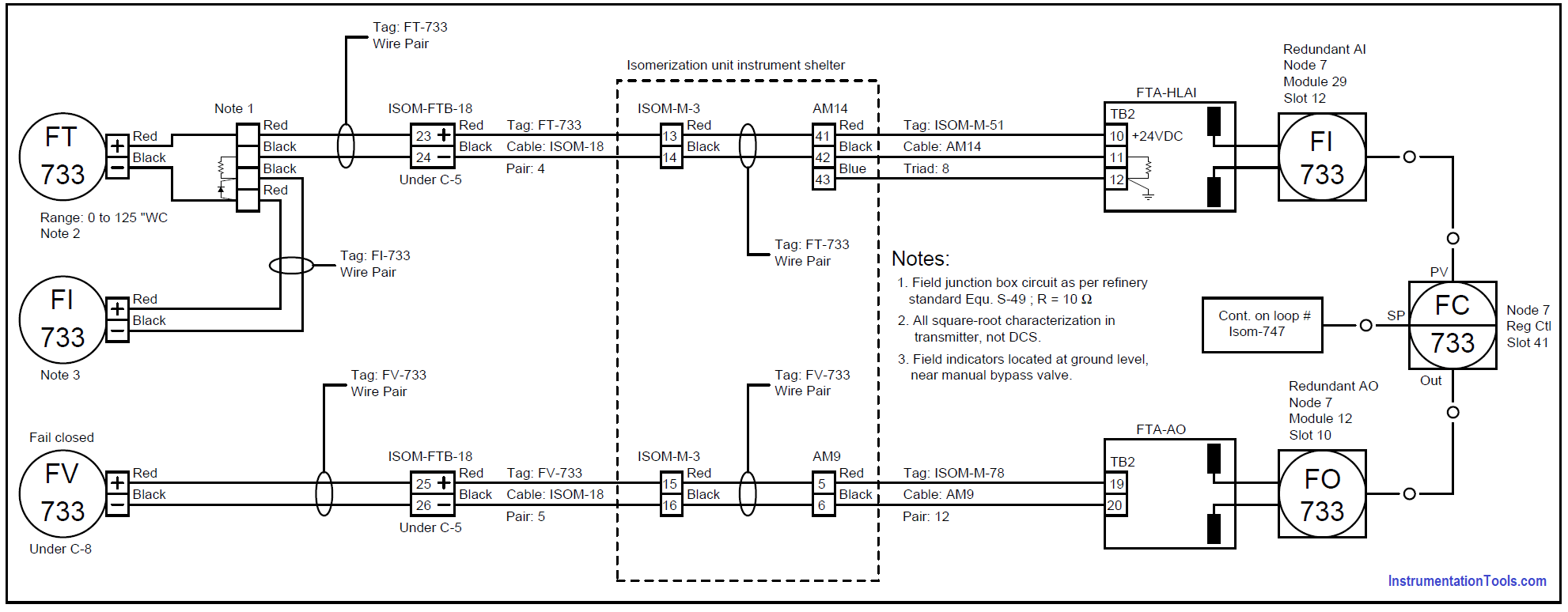
Loop Diagrams (Loop Sheets) | Control and Instrumentation Documentation | Automation Textbook
Pressure Control Loop Wiring Connections - Instrumentation Tools
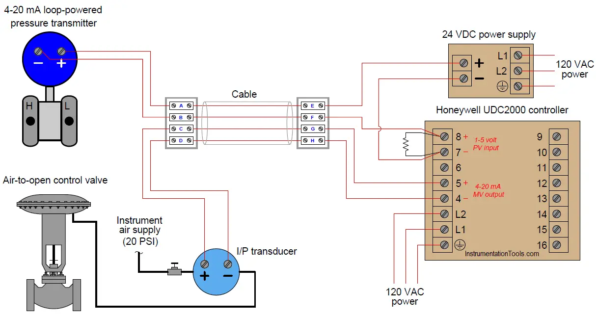
Instrumentation Loop Diagrams - InstrumentationTools
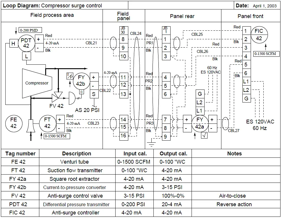
How-to Create Instrument loop diagram? | Marshalling Loop Diagrams

Instrumentation Diagrams Multiple Choice Questions Instrumentation Tools
Instrumentation Loop Diagrams - InstrumentationTools
