120v Rib Wiring Diagram
If more than one dry contact rib® shares a single dry contact input, A wiring diagram is a simple visual representation with the physical connections and physical layout of your electrical system or circuit.

FAQ Functional Devices, Inc.
On rib relay in a box 2401b wiring diagram.

120v rib wiring diagram. Isolation transformers for 24 vac circuits are also included. The power to energize the rib series comes from the load being controlled or a local power source near the relay. With this kind of an illustrative manual, you will have the ability to troubleshoot, prevent, and total your assignments with ease.
The pilot series contains relays that are rated at 10 or 15 amps. Relay in a box (rib) models are available to control most the rib has a protruding 1/2 npt nipple from which all wires exit (except t series). 120 volts switching relay wiring diagrams zone 1 zone 2 zone 3 fuse 1 amp z one 1 zone 2 zone 3 power zone 1 zone 2 n p zc h x1 x2 r com / 24 vac.
Each part ought to be placed and connected with other parts in specific way. Generally, 24 vac actuators over 100 va should be changed to 120 vac models. It shows what sort of electrical wires are interconnected which enable it to also show where fixtures and components may be connected to the system.
Zone valve wiring diagrams boiler wiring diagrams wiring for 4 wire zone valve low voltage 120 volts 120v 24v boiler connections t 1 t 2 3 zone valve hot neutral wiring for zone valve Not only will it help you achieve your required results more quickly, but in addition make the entire. All rib tr series transformers are ul listed.
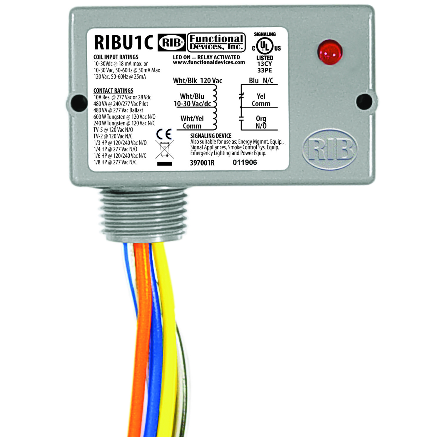
Our rib® relays are prepackaged to save you installation time and the expense of buying several components to assemble them on the job or at your shop. The functional devices rib tr series offers a complete line of control transformers for use in building automation and temperature control systems. • dry contact input operation:
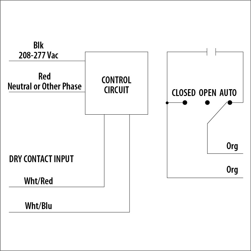
42 ma @ 120 vac notes: This means it can accept 24/120 voltage. The 120v to the booster fan passes through the switched contacts to start and stop the fan.
Close white/red wire to white/blue wire to activate relay. 28 images residential electrical wiring diagrams wiring diagram schematic diagram of electric motor wiring diagram and 25 best ideas about electrical wiring diagram on 25 best ideas about. Wiring the relay correctly is the most crucial step, if done incorrectly this could lead to a faulty relay in the future.
A wiring diagram is a straightforward visual representation with the physical connections and physical layout of your electrical system or circuit. Sy1 sy2 sy3 sy4 sy5 amps amps amps amps amps wire gauge 1.8 3 3 6 6.5 max distance between actuator and supply (feet) 18 92 55 55 16 144 87 87 43 40 14 233 140 140 70 65 12 357 214 214 107 99 10 606 364 364 182 168 8 905 543 543 271 250 the same conduit. The series includes transformer va ratings from 20 va up through 375 va and primary voltages of 120, 208, 240, 277, and 480 vac.
4.5 out of 5 stars. The relay contacts are isolated from the input power and the dry contact input. The switched contacts are shown in red wiring, terminals 3 and 5.
It shows how the electrical wires are interconnected and can also show where fixtures and components might be attached to the system. It is imperative wiring and ct placement is done exactly as indicated in the diagram. If one of the phases is grounded, wire that phase to the neutral (n) pin on the meter.
Otherwise, the structure will not work as it. The ribu1c is a versatile relay in a box and can be used for energizing posted in controls, functional. 24 vac/dc, 120 vac relays:
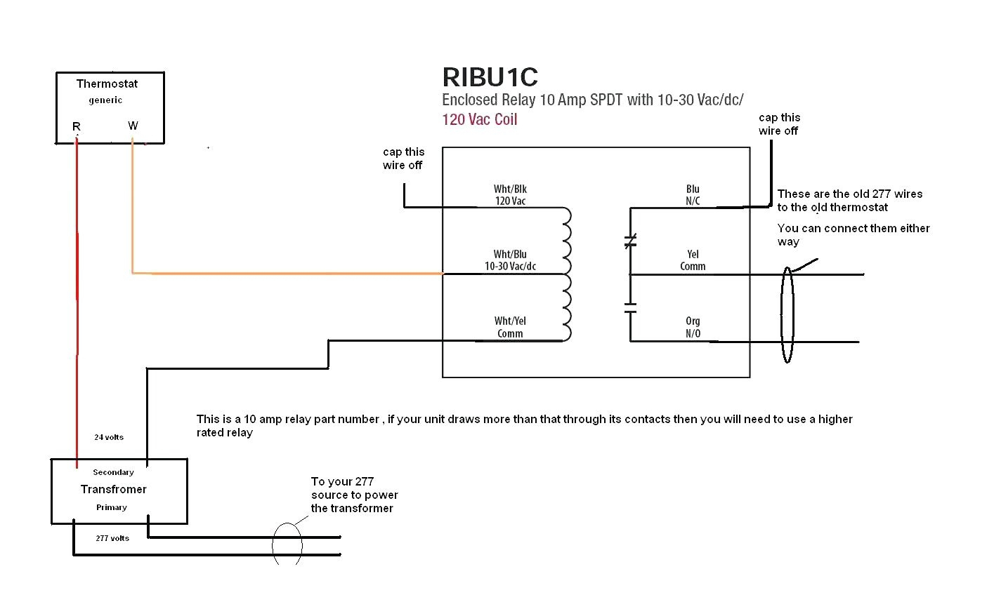
With this sort of an illustrative guidebook, you will have the ability to troubleshoot, stop, and total your assignments easily. The diagram below shows 120v being applied to the coil contacts (black wiring, terminals 7 and 8). From the functional devices website you can download rib relays data sheets, wiring diagrams, autocad drawings and visio drawings all.
With a clc closet switch you can use existing wiring to turn on the closet light just by to explain how to connect the ribu1c, we put together the following schematic.ribu1c wiring diagram wiring diagram need a rib relay wiring diagram how about a rib relay autocad drawing a rib relay visio drawing then you should know about a terrific resource. They have been packaged to save the installer the time, trouble and expense of buying separate components (relay, led. 240 watt tungsten @ 120 vac (n/c) 2 hp @ 277 vac 1 hp @ 120 vac rib01bdc enclosed relay 20 amp spdt, class 2 dry contact input, 120 vac power input power input:
Details Functional Devices, Inc.
480v To 120v Transformer Wiring Diagram

55 Rib Relay 24v Coil Wiring Diagram Wiring Diagram Harness

Rib Relays Faq Functional Devices Inc They are also known as functional devises inc.
20+ Latest 120v 2 Pole Contactor Wiring Diagram Stephan Fuchs

Wiring Diagram For 120v Coil Contactor Complete Wiring Schemas


120v 3 Phase Color Code 33

FAQ Functional Devices, Inc.

Ribu1C Wiring Diagram / Troubleshooting Rib Relays Functional Devices Inc A wiring diagram is
Rib Relay In A Box 2401b Wiring Diagram
120 Volt Relay Wiring Diagram / Ribu1c Rib Relays / To show you how to wire the relay, let's
RIBU1C Functional Devices RIBU1C Enclosed Pilot Relay, 10 Amp, SPDT w/ 1030 Vac/DC/120 Vac Coil


Double Switch Wire Diagram Fantastic Triple Single Pole Switch Wiring Diagram Free Download
Wiring Diagram For 120v Photocell schematic and wiring diagram


30 Fresh 120v Relay Wiring Diagram Home brewing, Home brewing equipment, Brewing
![]()
120v Wiring Diagram MERAH268
39 Timer Relay 120v Wiring Diagram Wiring Niche Ideas


How To Wire 3 Pleasing 480v 120v Transformer Wiring Diagram With Tearing 75 Kva Electrical

120v RIMS Wiring diagram. Look good? Wiring diagram, Diagram, Wire